302 lines
9.3 KiB
Markdown
302 lines
9.3 KiB
Markdown
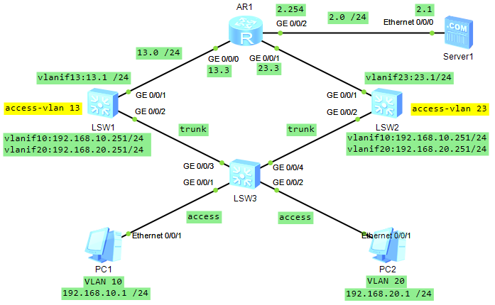
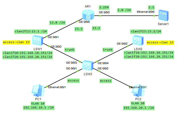
# 多VLAN环境下的VRRP负载分担
|
||
|
||
|
||
|
||
- **需求**
|
||
|
||
- SW1
|
||
|
||
```
|
||
备份组10:
|
||
SW1-master设备
|
||
作用:转发VLAN10用户上网数据
|
||
优先级:130
|
||
|
||
备份组20:
|
||
SW1-backup设备
|
||
作用:监控备份组20的master设备
|
||
优先级:默认100
|
||
```
|
||
|
||
- SW2
|
||
|
||
```
|
||
备份组10:
|
||
SW2-backup设备
|
||
作用:监控备份组10的master设备
|
||
优先级:默认100
|
||
|
||
备份组20:
|
||
SW2-master设备
|
||
作用:转发VLAN20用户上网数据
|
||
优先级:130
|
||
```
|
||
|
||
### 一、配置PC、服务器、路由的IP、子网掩码、网关
|
||
|
||
- **AR1**
|
||
|
||
```
|
||
[AR1]int g0/0/0
|
||
[AR1-GigabitEthernet0/0/0]ip add 192.168.13.3 24
|
||
[AR1-GigabitEthernet0/0/0]int g0/0/1
|
||
[AR1-GigabitEthernet0/0/1]ip add 192.168.23.3 24
|
||
[AR1-GigabitEthernet0/0/1]int g0/0/2
|
||
[AR1-GigabitEthernet0/0/2]ip add 192.168.2.254 24
|
||
```
|
||
|
||
### 二、配置交换机VLAN
|
||
|
||
- **SW3**
|
||
|
||
```
|
||
[SW3]vlan batch 10 20
|
||
[SW3]int g0/0/1
|
||
[SW3-GigabitEthernet0/0/1]port link-type access
|
||
[SW3-GigabitEthernet0/0/1]port default vlan 10
|
||
[SW3-GigabitEthernet0/0/1]int g0/0/2
|
||
[SW3-GigabitEthernet0/0/2]port link-type access
|
||
[SW3-GigabitEthernet0/0/2]port default vlan 20
|
||
[SW3-GigabitEthernet0/0/2]quit
|
||
[SW3]port-group group-member g0/0/3 g0/0/4
|
||
[SW3-port-group]port link-type trunk
|
||
[SW3-port-group]port trunk allow-pass vlan all
|
||
```
|
||
|
||
- **SW1**
|
||
|
||
```
|
||
[SW1]vlan 13
|
||
[SW1-vlan13]quit
|
||
[SW1-GigabitEthernet0/0/2]port link-type trunk
|
||
[SW1-GigabitEthernet0/0/2]port trunk allow-pass vlan all
|
||
[SW1-GigabitEthernet0/0/2]int g0/0/1
|
||
[SW1-GigabitEthernet0/0/1]port link-type access
|
||
[SW1-GigabitEthernet0/0/1]port default vlan 13
|
||
[SW1-GigabitEthernet0/0/1]quit
|
||
[SW1]int vlan 13
|
||
[SW1-Vlanif13]ip add 192.168.13.1 24
|
||
```
|
||
|
||
- **SW2**
|
||
|
||
```
|
||
[SW2]vlan 23
|
||
[SW2-vlan23]quit
|
||
[SW2]int g0/0/2
|
||
[SW2-GigabitEthernet0/0/2]port link-type trunk
|
||
[SW2-GigabitEthernet0/0/2]port trunk allow-pass vlan all
|
||
[SW2-GigabitEthernet0/0/2]int g0/0/1
|
||
[SW2-GigabitEthernet0/0/1]port link-type access
|
||
[SW2-GigabitEthernet0/0/1]port default vlan 23
|
||
[SW2-GigabitEthernet0/0/1]quit
|
||
[SW2]int vlan 23
|
||
[SW2-Vlanif13]ip add 192.168.23.1 24
|
||
```
|
||
|
||
### 三、配置VRRP
|
||
|
||
- **SW1**
|
||
|
||
```
|
||
[SW1]vlan batch 10 20
|
||
[SW1]int vlan 10
|
||
[SW1-Vlanif10]ip add 192.168.10.251 24
|
||
[SW1-Vlanif10]vrrp vrid 10 virtual-ip 192.168.10.254
|
||
[SW1-Vlanif10]vrrp vrid 10 priority 130
|
||
[SW1-Vlanif10]vrrp vrid 10 track int g0/0/1 reduced 50
|
||
[SW1-Vlanif10]int vlan 20
|
||
[SW1-Vlanif20]ip add 192.168.20.251 24
|
||
[SW1-Vlanif20]vrrp vrid 20 virtual-ip 192.168.20.254
|
||
```
|
||
|
||
- *注解*
|
||
1. `[SW1]int vlan 10`:进入交换机 SW1 的配置模式,并创建或进入 VLAN 10 的接口配置。
|
||
2. `[SW1-Vlanif10]ip add 192.168.10.251 24`:为 VLAN 10 的虚拟接口配置 IP 地址 192.168.10.251,子网掩码为 24 位。
|
||
3. `[SW1-Vlanif10]vrrp vrid 10 virtual-ip 192.168.10.254`:在 VLAN 10 上配置 VRRP,设置虚拟路由器 ID 为 10,并指定虚拟 IP 地址为 192.168.10.254。
|
||
4. `[SW1-Vlanif10]vrrp vrid 10 priority 130`:设置 VRRP 虚拟路由器 10 的优先级为 130。
|
||
5. `[SW1-Vlanif10]vrrp vrid 10 track int g0/0/1 reduced 50`:配置 VRRP 跟踪功能,监视接口 g0/0/1 的状态。如果该接口故障,VRRP 的优先级将减少 50。
|
||
6. `[SW1]int vlan 20`:创建或进入 VLAN 20 的接口配置。
|
||
7. `[SW1-Vlanif20]ip add 192.168.20.251 24`:为 VLAN 20 的虚拟接口配置 IP 地址 192.168.20.251,子网掩码为 24 位。
|
||
8. `[SW1-Vlanif20]vrrp vrid 20 virtual-ip 192.168.20.254`:在 VLAN 20 上配置 VRRP,设置虚拟路由器 ID 为 20,并指定虚拟 IP 地址为 192.168.20.254。
|
||
|
||
- **SW2**
|
||
|
||
```
|
||
[SW2]vlan batch 10 20
|
||
[SW2]int vlan 10
|
||
[SW2-Vlanif10]ip add 192.168.10.252 24
|
||
[SW2-Vlanif10]vrrp vrid 10 virtual-ip 192.168.10.254
|
||
[SW2-Vlanif10]int vlan 20
|
||
[SW2-Vlanif20]ip add 192.168.20.252 24
|
||
[SW2-Vlanif20]vrrp vrid 20 virtual-ip 192.168.20.254
|
||
[SW2-Vlanif20]vrrp vrid 20 priority 130
|
||
[SW2-Vlanif20]vrrp vrid 20 track int g0/0/1 reduced 50
|
||
```
|
||
|
||
- *注解*
|
||
1. `[SW2]int vlan 10`:进入交换机 SW2 的配置模式,并创建或进入 VLAN 10 的接口配置。
|
||
2. `[SW2-Vlanif10]ip add 192.168.10.252 24`:为 VLAN 10 的虚拟接口配置 IP 地址 192.168.10.252,子网掩码为 24 位。
|
||
3. `[SW2-Vlanif10]vrrp vrid 10 virtual-ip 192.168.10.254`:在 VLAN 10 上配置 VRRP,设置虚拟路由器 ID 为 10,并指定虚拟 IP 地址为 192.168.10.254(与 SW1 上的配置相同)。
|
||
4. `[SW2]int vlan 20`:创建或进入 VLAN 20 的接口配置。
|
||
5. `[SW2-Vlanif20]ip add 192.168.20.252 24`:为 VLAN 20 的虚拟接口配置 IP 地址 192.168.20.252,子网掩码为 24 位。
|
||
6. `[SW2-Vlanif20]vrrp vrid 20 virtual-ip 192.168.20.254`:在 VLAN 20 上配置 VRRP,设置虚拟路由器 ID 为 20,并指定虚拟 IP 地址为 192.168.20.254(与 SW1 上的配置相同)。
|
||
7. `[SW2-Vlanif20]vrrp vrid 20 priority 130`:设置 VRRP 虚拟路由器 20 的优先级为 130。
|
||
8. `[SW2-Vlanif20]vrrp vrid 20 track int g0/0/1 reduced 50`:配置 VRRP 跟踪功能,监视接口 g0/0/1 的状态。如果该接口故障,VRRP 的优先级将减少 50。
|
||
|
||
- **总结**
|
||
|
||
- VLAN 10 和 VLAN 20 都在两台交换机上配置了 VRRP,虚拟 IP 地址分别为 192.168.10.254 和 192.168.20.254。
|
||
- 在 VLAN 10 上,SW1 的优先级高于 SW2,因此 SW1 将成为主网关。
|
||
- 在 VLAN 20 上,SW2 的优先级被设置为 130,高于 SW1 的默认优先级(通常为 100),因此 SW2 将成为主网关。
|
||
- 如果 g0/0/1 接口故障,那么拥有该接口的交换机的 VRRP 优先级将降低,可能导致主备角色切换。
|
||
|
||
### 四、静态路由
|
||
|
||
- **SW1**
|
||
|
||
```
|
||
[SW1]ip route-static 192.168.2.0 24 192.168.13.3
|
||
```
|
||
|
||
- **SW2**
|
||
|
||
```
|
||
[SW2]ip route-static 192.168.2.0 24 192.168.23.3
|
||
```
|
||
|
||
- **AR1**
|
||
|
||
```
|
||
[AR1]ip route-static 192.168.10.0 24 192.168.13.1
|
||
[AR1]ip route-static 192.168.10.0 24 192.168.23.1 preference 100
|
||
[AR1]ip route-static 192.168.20.0 24 192.168.13.1 preference 100
|
||
[AR1]ip route-static 192.168.20.0 24 192.168.23.1
|
||
```
|
||
|
||
### 五、连通性测试
|
||
|
||
- **PC1**
|
||
|
||
- PING 服务器
|
||
|
||
```
|
||
PC1>ping 192.168.2.1
|
||
|
||
Ping 192.168.2.1: 32 data bytes, Press Ctrl_C to break
|
||
From 192.168.2.1: bytes=32 seq=1 ttl=253 time=47 ms
|
||
From 192.168.2.1: bytes=32 seq=2 ttl=253 time=47 ms
|
||
From 192.168.2.1: bytes=32 seq=3 ttl=253 time=63 ms
|
||
From 192.168.2.1: bytes=32 seq=4 ttl=253 time=62 ms
|
||
From 192.168.2.1: bytes=32 seq=5 ttl=253 time=47 ms
|
||
|
||
--- 192.168.2.1 ping statistics ---
|
||
5 packet(s) transmitted
|
||
5 packet(s) received
|
||
0.00% packet loss
|
||
round-trip min/avg/max = 47/53/63 ms
|
||
```
|
||
|
||
- Tracert 服务器
|
||
|
||
```
|
||
PC1>tracert 192.168.2.1
|
||
|
||
traceroute to 192.168.2.1, 8 hops max
|
||
(ICMP), press Ctrl+C to stop
|
||
1 192.168.10.251 16 ms 46 ms 47 ms
|
||
2 192.168.13.3 63 ms 62 ms 78 ms
|
||
3 192.168.2.1 63 ms 62 ms 63 ms
|
||
```
|
||
|
||
- **PC2**
|
||
|
||
- PING 服务器
|
||
|
||
```
|
||
PC2>ping 192.168.2.1
|
||
|
||
Ping 192.168.2.1: 32 data bytes, Press Ctrl_C to break
|
||
From 192.168.2.1: bytes=32 seq=1 ttl=253 time=62 ms
|
||
From 192.168.2.1: bytes=32 seq=2 ttl=253 time=63 ms
|
||
From 192.168.2.1: bytes=32 seq=3 ttl=253 time=78 ms
|
||
From 192.168.2.1: bytes=32 seq=4 ttl=253 time=78 ms
|
||
From 192.168.2.1: bytes=32 seq=5 ttl=253 time=47 ms
|
||
|
||
--- 192.168.2.1 ping statistics ---
|
||
5 packet(s) transmitted
|
||
5 packet(s) received
|
||
0.00% packet loss
|
||
round-trip min/avg/max = 47/65/78 ms
|
||
```
|
||
|
||
- Tracert 服务器
|
||
|
||
```
|
||
PC2>tracert 192.168.2.1
|
||
|
||
traceroute to 192.168.2.1, 8 hops max
|
||
(ICMP), press Ctrl+C to stop
|
||
1 192.168.20.252 31 ms 47 ms 31 ms
|
||
2 192.168.23.3 62 ms 79 ms 62 ms
|
||
3 192.168.2.1 63 ms 62 ms 63 ms
|
||
```
|
||
|
||
### 六、功能性测试
|
||
|
||
- **左侧上行线断连**
|
||
|
||

|
||
|
||
- PC1 Tracert 服务器
|
||
|
||
```
|
||
PC1>tracert 192.168.2.1
|
||
|
||
traceroute to 192.168.2.1, 8 hops max
|
||
(ICMP), press Ctrl+C to stop
|
||
1 192.168.10.252 47 ms 47 ms 47 ms
|
||
2 192.168.23.3 78 ms 62 ms 63 ms
|
||
3 192.168.2.1 78 ms 62 ms 63 ms
|
||
```
|
||
|
||
- PC2 Tracert 服务器
|
||
|
||
```
|
||
PC2>tracert 192.168.2.1
|
||
|
||
traceroute to 192.168.2.1, 8 hops max
|
||
(ICMP), press Ctrl+C to stop
|
||
1 192.168.20.252 62 ms 47 ms 47 ms
|
||
2 192.168.23.3 62 ms 63 ms 62 ms
|
||
3 192.168.2.1 78 ms 63 ms 62 ms
|
||
```
|
||
|
||
- **右侧上行线断连**
|
||
|
||
|
||
|
||
- PC1 Tracert 服务器
|
||
|
||
```
|
||
PC1>tracert 192.168.2.1
|
||
|
||
traceroute to 192.168.2.1, 8 hops max
|
||
(ICMP), press Ctrl+C to stop
|
||
1 192.168.10.251 78 ms 31 ms 47 ms
|
||
2 192.168.13.3 109 ms 78 ms 63 ms
|
||
3 192.168.2.1 62 ms 63 ms 62 ms
|
||
```
|
||
|
||
- PC2 Tracert 服务器
|
||
|
||
```
|
||
PC2>tracert 192.168.2.1
|
||
|
||
traceroute to 192.168.2.1, 8 hops max
|
||
(ICMP), press Ctrl+C to stop
|
||
1 192.168.20.251 93 ms 32 ms 46 ms
|
||
2 192.168.13.3 63 ms 62 ms 79 ms
|
||
3 192.168.2.1 62 ms 94 ms 62 ms
|
||
```
|